Get Access Point Placement Right First Time for UK Offices and Homes
14 September 2026
Get Access Point Placement Right First Time for UK Offices and Homes
Mount access points centrally on the ceiling above the area they serve, favour several low-power cells over one powerful unit, and never trust a floor-plan sketch until a walk test confirms it. Get the central positioning and mounting height right first; everything else, from channel planning to PoE budgeting, is fine-tuning around that one decision.
TL;DR:
- Proper access point placement requires central ceiling mounting above the area, with height and positioning confirmed through walk tests rather than floor plans alone.
- Ceiling mounting provides more uniform coverage, but when wall mounting is necessary, mount units high and face into the room, avoiding metal obstructions.
- Use predictive surveys and active site testing to determine the exact number and optimal locations, especially in buildings with heavy concrete or metal structures.
- Minimize signal bleed outside the property by orienting antennas inward and reducing transmit power near boundaries to enhance security.
- Deploy multiple lower-power access points rather than fewer high-power units to prevent interference, improve roaming, and better handle device density.
Table of Contents
- Access point placement basics: how Wi-Fi signal actually behaves
- Ceiling mount, wall mount, or somewhere else entirely?
- How do you plan access point placement before installing anything?
- How many access points do you actually need?
- Cabling, PoE budgets and equipment choices that shape your layout
- Interference and channel planning around your placement
- Testing and validating your access point placement
- Dual-band vs single-band: which placement strategy fits?
- Keeping your Wi-Fi signal inside your property boundary
- Fitting access points into your existing network and VLAN plan
- What the placement guides usually leave out
- Get your access points placed properly the first time
- Sources
- FAQ
Access point placement basics: how Wi-Fi signal actually behaves
Every access point placement decision comes down to a trade-off between range and penetration. 2.4 GHz travels further and pushes through walls more easily, which is exactly why it gets more congested. 5 GHz carries more data but loses strength faster once it hits obstacles, and 6 GHz (now open for Wi-Fi use in the UK following Ofcom’s decision to release the full 6 GHz band) behaves the same way but more so: fast, clean, and short-lived once it meets a solid obstruction.
Building materials matter more than most installers admit. Lab testing found that concrete walls cut Wi-Fi electric field strength by roughly half at 2.4 GHz and a substantial decrease at 5 GHz in some test setups(https://doi.org/10.4236/jcc.2024.125001), confirming that higher frequencies suffer disproportionately once concrete gets involved. Glass, by contrast, barely dents a signal. That asymmetry explains why an open-plan office with glass partitions performs beautifully while a Victorian house with solid brick internal walls needs an access point on nearly every floor.
Materials that cause the biggest headaches for access point placement:
- Reinforced concrete and breeze block walls
- Metal cladding, filing cabinets, and lift shafts
- Underfloor heating pipework and ducting
- Wire mesh in plaster (common in older commercial buildings)
- Large mirrors or foil-backed insulation
Coverage is not the same problem as capacity. A single access point might show full bars across a 40-person open office on a predictive heatmap, yet still choke the moment 35 laptops, 20 phones, and a dozen VoIP handsets all try to associate with it at once. That’s an insight worth sitting with: many businesses add access points not because signal is weak, but because too many devices are fighting for airtime on too few radios.
Ceiling mount, wall mount, or somewhere else entirely?
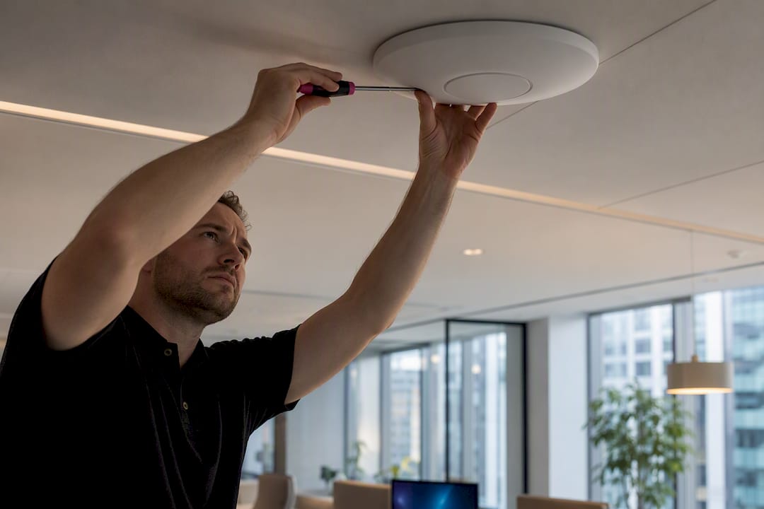
Ceiling mounting wins in almost every commercial and most residential scenarios, and the logic is simple: mounted centrally over the area it serves, an access point radiates signal downward and outward with minimal obstruction, covering desks, aisles, and open floor space evenly. Wall mounting works, but only when ceiling access is genuinely impractical, and it comes with rules of its own.
Placement rules worth following
- Centre the access point over the space it serves, not over a corridor or a stairwell that nobody sits in.
- Mount ceiling units flush or with a short drop antenna, angled so the radiation pattern spreads across the room rather than up into the void above a suspended ceiling.
- When wall-mounting is unavoidable, fit the unit high, around 2 to 2.4 metres, and orient it to face into the room rather than along a wall.
- Avoid mounting near metal cabinets, lift shafts, or ducting even when the wall itself looks harmless.
- Never tuck an access point inside a cupboard or comms cabinet purely to hide it. It will attenuate signal for everyone on the far side of that door.
- Keep antennas away from large mirrors or glass partitions with metallic film, which reflect and scatter signal unpredictably.
The most common mistake is placing units where they’re convenient to run a cable to, rather than where the users actually sit. A reception desk in the corner of a building gets its own access point because a cable happened to terminate there, while the open-plan area 15 metres away, packed with staff, limps along on a weak signal from that same corner unit. Corners are almost always the wrong answer: half the coverage cell is wasted outside the building or into an empty stairwell.
Aesthetics do matter, particularly in client-facing spaces, but disguising an access point behind a false ceiling tile or inside a decorative box usually costs more in signal than it saves in appearance. The better compromise is a low-profile ceiling unit finished in white, mounted flush, which most visitors never notice anyway.
Pro Tip: Choose a mounting point that’s accessible with a standard step ladder, not one that needs scaffold or a ceiling tile prised out with force. Access points need firmware updates and occasional resets, and a unit nobody can reach becomes a unit nobody maintains.
How do you plan access point placement before installing anything?
Start with a predictive survey rather than guesswork. Tools like Ekahau’s Auto-Planner and NetSpot’s predictive survey mode let you import a floor plan, assign wall materials, drop in virtual access points, and generate a coverage heatmap before a single cable gets pulled. Both platforms let you import vendor-specific antenna files so the modelled coverage shape reflects the actual radiation pattern of the hardware you plan to install, rather than assuming a generic omnidirectional bubble.
Predictive modelling is genuinely useful for early planning and for costing out cable runs, but treat its output as a hypothesis, not a guarantee. The same guidance from Ekahau is explicit that predictive results need validating with an active, on-site survey once the building is more complex than a simple square floor plan. Concrete lift shafts, thick server room walls, and unexpected metal ductwork rarely show up accurately on a plan drawn from an architect’s PDF.
An active survey, sometimes called an “AP on a stick” survey, involves temporarily mounting a real access point at each candidate location and walking the space with a laptop or dedicated survey tool to measure actual signal strength, not modelled signal strength. For anything beyond a small home or a single open-plan office, this remains the gold standard.
A sensible sequence looks like this:
- Draft a floor plan and mark where people actually work, not just where sockets exist
- Run a predictive survey to generate an initial coverage and capacity heatmap
- Use that heatmap to plan cable runs and PoE switch requirements
- Run an active survey once cabling is in place to confirm real-world performance
- Finalise access point positions and lock in the channel plan
The deliverables from this process, a coverage heatmap, a capacity heatmap, recommended positions, and a PoE point list, become the reference document for anyone maintaining the network later.
How many access points do you actually need?
There’s no single number that fits every building, because device density drives the answer more than square footage does. A quiet home office with two laptops and a smart TV might run fine on one well-placed unit. A 20-desk business with laptops, mobiles, and VoIP handsets on every desk often needs two or three units to comfortably split that load, even though one access point could technically “cover” the same square metres on paper.
Rough starting points that hold up in practice:
- Homes under 100 square metres with standard stud walls: one central access point, two if the property has solid internal walls or three floors
- Small offices (10 to 20 people): one access point per 15 to 20 users, biased toward device count rather than floor area
- Open-plan offices and warehouses: plan per zone using a predictive heatmap, then verify with an active survey
- Any space with heavy concrete or brick partitioning: add roughly 30 to 50% more units than a stud-wall equivalent would need
For roaming to work properly, cell overlap should sit around 15 to 20%, and heatmap best practice recommends that at least two access points remain visible at −72 dBm or stronger along any walking path. That figure matters because devices roam between access points based on signal strength thresholds set by the 802.11k/v/r standards, and if a device drops below a usable signal before the next access point picks it up, calls cut out and video streams stutter.
One instinct worth resisting: cranking transmit power up to “cover more ground” with fewer units. Overpowered access points create wide, overlapping cells that fight each other on the same channel, and they encourage what’s known as the sticky client problem, where a phone or laptop clings to a distant, weakening access point instead of roaming to a closer one. The fix is usually the opposite of what feels intuitive: more access points, each running at lower power, rather than fewer units shouting louder.
Cabling, PoE budgets and equipment choices that shape your layout
Access point placement is only as good as the cabling that reaches it. Run Cat6a wherever possible, even if current access points only need Cat6, because Wi-Fi 6E and Wi-Fi 7 units increasingly want multi-gig backhaul to avoid the AP radio outrunning the switch port. A £2,000 access point plugged into a 1 Gbps port with three radios pushing traffic will bottleneck long before the radios ever get maxed out.
Follow these steps when planning power and cabling:
- Match PoE class to the access point’s actual draw. Basic dual-band units often run fine on 802.3af, but Wi-Fi 6 and 6E units with multiple radios typically need 802.3at or 802.3bt.
- Calculate the switch’s total PoE budget, not just its per-port rating. A 24-port switch rated for 370 watts total will not deliver full power to 24 high-draw access points simultaneously.
- Centralise PoE at the switch rather than using injectors scattered around the building, which are harder to monitor and more likely to fail quietly.
- Plan cable routes before mounting positions are finalised, since a perfect access point location that needs 90 metres of cable run through three fire-rated walls isn’t actually practical.
- For outdoor or industrial locations, choose access points with an appropriate IP rating and weatherproof PoE connectors, and mount them under eaves or in enclosures rated for the environment.
A properly specified cabling and PoE plan avoids the single most common post-installation complaint: an access point that keeps rebooting because the switch port it’s plugged into can’t sustain the power draw once the unit is under full load. A network cabling specialist can size the switch and cable runs correctly before installation day rather than after the complaints start.
Interference and channel planning around your placement
Good placement can still underperform if the channel plan is a mess. On 2.4 GHz, stick to channels 1, 6, and 11, the only three that don’t overlap, and never let auto-channel selection drift onto anything between them. On 5 GHz, plan channel width conservatively, 20 or 40 MHz in dense deployments rather than 80 MHz, since wider channels mean fewer non-overlapping options and more co-channel contention between your own access points.
Watch for DFS channels on 5 GHz too. These share spectrum with radar systems, and an access point can suddenly switch channels mid-session if it detects radar activity, causing a brief but noticeable disconnection. In areas near airports or weather stations, this happens more often than installers expect.
Common interference sources to check before blaming the access point itself:
- Neighbouring businesses’ Wi-Fi networks on overlapping channels
- Microwave ovens and older cordless phones on 2.4 GHz
- Bluetooth devices in dense clusters
- Metal shelving or machinery causing multipath reflections
- Baby monitors and wireless CCTV cameras on residential networks
A spectrum analyser, or the built-in scanning tools in Ekahau and NetSpot, will show you exactly what’s occupying each channel before you commit to a plan. Reassign channels after reviewing the heatmap, not before, since the heatmap tells you which access points actually overlap enough to cause a problem. Tie this back to spacing and power: two access points on the same channel, placed too close together and running full power, will always interfere more than the same two units spaced further apart and tuned down.
Testing and validating your access point placement
A walk test is the final proof that placement decisions actually worked. Walk every route staff or customers use, laptop or phone in hand, running a Wi-Fi analyser app, and log signal strength, throughput, and packet loss at regular intervals.
- Record RSSI (signal strength in dBm) every few metres along normal walking routes, not just at desks.
- Check throughput at the furthest point of each coverage cell, not just near the access point itself.
- Log packet loss and latency, particularly if VoIP or video calling matters to the business.
- Confirm roaming works by making a call or streaming video while walking between coverage cells, listening for drops or stutters.
- Document every result with a heatmap export and handover notes so facilities teams know what “normal” looks like for future troubleshooting.
Acceptance criteria worth setting before you call the job finished: signal at or above −72 dBm along all walking paths, packet loss under 5%, and a VoIP mean opinion score that stays acceptable through a full roaming handoff. If any of those fail, the fix is rarely a brand new access point. It’s usually retuning transmit power, nudging a unit a few metres, or correcting a channel overlap you missed during planning.
Pro Tip: Keep the original heatmap and walk test results on file. When someone adds a new stud wall or a bank of filing cabinets eighteen months later and coverage suddenly drops, you’ll have a baseline to compare against instead of guessing what changed.
Dual-band vs single-band: which placement strategy fits?
Most modern access points are dual-band or tri-band, broadcasting 2.4 GHz and 5 GHz (and increasingly 6 GHz) from the same unit, which simplifies placement considerably: one physical location serves both bands, and client devices choose whichever performs better. Single-band 2.4 GHz-only units still exist for cost-sensitive deployments or specific IoT use cases, but they force a harder placement decision because you’re relying entirely on a band with more range but less capacity.
For most homes and offices, dual-band placement following the same central, ceiling-mounted rules covers both frequencies adequately, since 5 GHz simply has a smaller effective cell size within the same physical location. The practical adjustment is spacing: if capacity on 5 GHz matters (video calls, large file transfers, dense device counts), you may need slightly tighter spacing between units than a 2.4 GHz-only plan would require, because that band’s coverage radius shrinks faster once it meets walls or distance.
Where single-band placement still makes sense is dedicated IoT networks, smart locks, sensors, and low-bandwidth devices that don’t need 5 GHz speed and benefit from 2.4 GHz’s better wall penetration. Some businesses deploy a lighter grid of 2.4 GHz-only units specifically for this traffic, separate from the primary dual-band grid serving staff and guests, which also keeps low-priority device chatter off the main network’s higher-capacity radios.
Keeping your Wi-Fi signal inside your property boundary
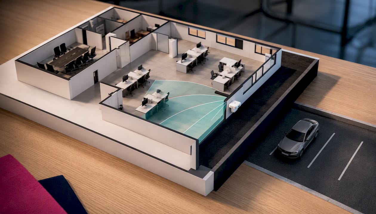
Signal bleed, Wi-Fi reaching the car park, next door’s office, or the street outside, isn’t just a coverage inefficiency. It’s a security exposure, since anyone within range can attempt to associate with the network or capture traffic for later analysis. Placement is the first line of defence here, well ahead of any firewall setting.
Avoid mounting access points against external walls facing public areas unless the coverage genuinely needs to reach outdoor space like a loading bay or car park with staff devices. Where an access point must sit near a perimeter wall, orient the antenna pattern inward and consider reducing transmit power on that specific unit rather than running every access point in the building at identical strength. A directional or sector antenna, rather than an omnidirectional one, can also shape coverage away from a boundary.
Beyond physical placement, treat guest and public-facing Wi-Fi as a separate network entirely, isolated from internal systems, so even if signal does reach beyond the building, whoever connects to it can’t see internal traffic or devices. Regularly re-run a simple signal check from the car park or pavement outside the building. If a laptop can pick up a strong signal from the street, that’s a placement or power setting worth revisiting immediately, not a problem to leave for the next scheduled review.
Fitting access points into your existing network and VLAN plan
Access point placement decisions don’t happen in isolation from the rest of the network. Every unit needs to plug into a switch port that’s correctly configured for the VLANs it will carry, and getting this wrong is one of the most common causes of “the Wi-Fi is fine but nothing works” support calls.
A typical business setup separates traffic into at least three VLANs: a staff VLAN with access to internal servers and printers, a guest VLAN with internet-only access and no visibility of internal systems, and increasingly a dedicated VLAN for VoIP handsets to guarantee call quality isn’t competing with someone’s video call for the same airtime priority. Modern access points broadcast multiple SSIDs, each mapped to its own VLAN, from the same physical hardware, so the placement decision and the network segmentation decision need to be made together rather than one after the other.
This matters most at the switch port each access point connects to. That port needs to be configured as an 802.1Q trunk carrying all the relevant VLAN tags, not a simple access port, otherwise the access point can only serve a single network regardless of how many SSIDs it broadcasts. Getting this configuration wrong is invisible on a heatmap: signal strength looks perfect, but guest devices end up on the internal network or VoIP traffic gets no priority at all. It’s worth confirming VLAN tagging and trunk configuration as part of the same walk test that checks signal strength, not as an afterthought once coverage looks good.
What the placement guides usually leave out
Most access point placement guidance assumes a blank slate: an empty building, a clean floor plan, and infinite budget for cabling. Real buildings rarely offer that. Businesses inherit awkward cable runs from previous tenants, listed buildings that won’t allow new penetrations through original brickwork, and budget constraints that mean the “ideal” six-access-point layout gets trimmed to four.
What tends to get underestimated is how much placement quality depends on decisions made weeks before installation, not on the day itself. The floor plan review that spots a concrete lift shaft, the conversation about where staff will actually sit once the office is reconfigured, the PoE switch that gets specified with headroom for growth rather than the bare minimum for today’s device count. None of that shows up in a coverage heatmap, but all of it determines whether the network still performs well eighteen months later.
The other pattern worth naming: businesses treat placement as a one-off decision rather than something that needs revisiting. Furniture gets rearranged, staff headcount grows, someone installs a metal partition for a new meeting room, and suddenly a network that tested perfectly at handover has a dead zone nobody planned for. A properly documented walk test and heatmap from the original installation makes that kind of drift easy to diagnose. Without one, every future problem starts from zero.
— Paul
Get your access points placed properly the first time
Reading a guide gets you most of the way there, but a concrete lift shaft, an oddly shaped office, or a listed building with restrictions on cable runs will always throw up something a floor plan alone can’t predict. Essex Telephone Systems runs on-site Wi-Fi surveys for businesses across Essex, London, and the South East, producing the coverage heatmap, capacity heatmap, and recommended access point positions this guide has described, backed by a proper cabling and PoE plan rather than a best guess.

A Wi-Fi survey tells you exactly how many access points your building needs and precisely where they should go, before anyone drills a hole or runs a cable. Where the survey identifies cabling gaps or PoE switch upgrades, our network cabling team handles the installation end to end, so the plan on paper matches what actually gets fitted. If your business also runs on VoIP handsets, it’s worth checking your VoIP setup at the same time, since call quality depends on the same placement and VLAN decisions covered in this guide. Get in touch to book a site survey and find out exactly what your building needs.
Sources
- Ofcom green lights UK Wi‑Fi access across entire 6 GHz band — Computer Weekly
- Creating a network plan with Auto‑Planner — Ekahau support
- WiFi heat map guide — Purple
- How many WiFi access points do you need? AP placement & PoE guide — Prodisk Network
FAQ
Where should I put my access point?
Mount it centrally, on the ceiling, over the area with the most devices, not in a corner or a cupboard. Avoid metal cabinets, ducting, and thick concrete walls wherever possible.
What’s the difference between a Wi-Fi extender and an access point?
An extender rebroadcasts an existing signal wirelessly, usually halving throughput in the process, while an access point connects via cable to your network and broadcasts a full-strength signal of its own. For anything beyond a small flat, a wired access point almost always outperforms an extender.
Where should I avoid placing a router or access point?
Avoid corners, closets, behind metal filing cabinets, near large mirrors, and anywhere requiring specialist access like above a high ceiling needing scaffold. These spots waste coverage or make maintenance impractical.
How far apart should access points be?
The exact distance depends on building materials and device density, which is why a proper survey beats a fixed metre figure.
How many access points does a typical small office need?
Plan on roughly one access point per multiple users, focusing on device density rather than floor area alone, increasing the count for solid internal walls or areas with high device density. A predictive survey followed by an active walk test gives you the precise number for your specific layout.